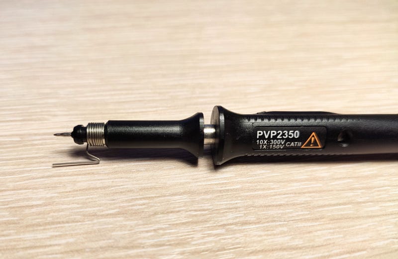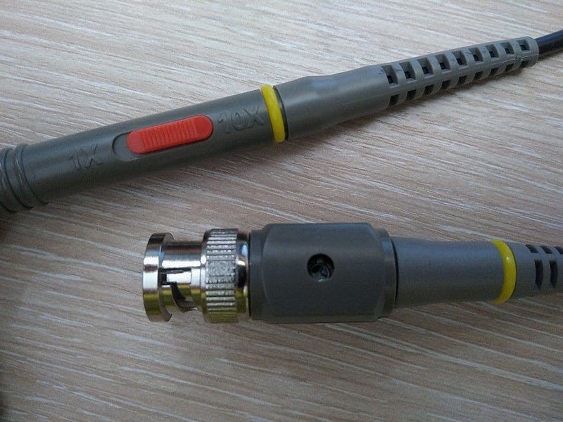
TL;DR: make sure to always use 1:10 probe with bandwidth of at least 1.5 times greater than that of the signal measured and of the oscilloscope. For high-speed use spring ground connection.
Bandwidth (BW) of a measurement setup is defined not only by the ADC and the front end of the oscilloscope: there is also theprobe, and its effect can be much higher. A good probe is of absolute importance when you deal with high-frequency (HF) measurements or sharp-edged digital signals (even a “slow” 10 kHz signal with 2 ns rise time has actual BW of 175 MHz).
Low-end scopes come with just 1MΩ || 15 pF inputs, and their full bandwidth cannot be achieved without a special probe. The most common one is an x10 passive probe with capacitive compensation, also known as “10x” or “1:10”.
To keep the total system’s bandwidth high (that is, limited by the scope, not by the probe), it’s recommended to use a probe with a specified BW at least 1.5 times higher than the BW of the scope. For example, if your oscilloscope is 100 MHz, buy 150 MHz probes.
Inside a probe
A passive probe is not just a piece of wire, it’s a complex device with both active and reactive elements inside. Rdiv resistor inside the probe and Rin inside the scope make up a voltage divider 10:1. To maintain this ratio for AC voltage, Ccomp capacitor is connected in parallel with Rdiv. It makes up a similar voltage divider with Cin (internal scope capacitance) and cable capacitance. Ccomp prevents high-frequency signals from most of the attenuation by the RC low-pass filter (which is there because of Rdiv and Cin plus cable capacitance).

Sometimes Ccomp inside the handle is made non-adjustable — instead, there is a trimmer capacitor near the BNC connector of the probe (which would be parallel with the Cin). Same idea— but slightly different implementation.

In a 1x probe there is no Rdiv resistor (or it is shorted with a switch), so there is no capacitance compensation and no resistive voltage divider. That’s why x1 probes have a much lower BW, usually about 5 MHz.
How to measure
It’s easy to screw up the measurement by not using the probe right. For any HF signal measurement with a passive probe an engineer should:
- For almost any signals — both digital and analog — use an x10 probe with 1MΩ scope input. Check that the switch on the probe (if any) is at x10, not at x1: the bandwidth of x1 probes is only about 5 MHz.
- Adjust probe compensation circuit before measurement. Scopes usually have a special port for the test output signal (5V/1kHz).
- Keep in mind that for HF signals the probe is not invisible. x10 probe has an input capacitance of around 5…15 pF, and it can totally wreck a high-frequency analog circuit. There are circuits which are sensitive even for small fractions of pF. Probing a non-inverting input or an output of a 500 MHz opamp will cause self-excitation.
- Use a small metal spring (and not the alligator clip) to make a short ground connection between probe ground and circuit ground. The closer ground to tip, the better. Excessive inductance of the ground loop formed by an alligator clip (100–300 nH) will cause ringing. The effect is noticeable even at 10 MHz (rise time <35 ns).
- Connect the probe tip directly to the target point. There might be a hook tip which comes with the probe, but use it with caution and preferably for slow signals only. Every extra centimeter of wire will introduce more inductance and cause ringing. If you still want to use a hook tip, at least keep all the wires short (5 cm or less).
Passive probes and 50 Ω circuits
Use of passive probes in 50 Ω circuits is a really delicate matter. Most of the high-frequency circuits, especially RF ones, are designed to be used in the 50 Ω systems. These circuits expect either 100 Ω of total load at output (if series termination is used) or sometimes 50 Ω (if output is low-impedance). Series termination is usually omitted in the high-power amplifiers because of power dissipation. The input impedance of the probe is neither 50 Ω nor 100 Ω, nor is it high enough to be neglected.
The only correct way to measure the output signal of the 50 Ω HF/RF stage is to connect it to the embedded 50 Ω scope input with a 50 Ω cable; if the output power is high —an attenuator should be used in between. Sadly, low-end scopes have no 50 Ω input, so I’ll describe measurements with a passive probe. There is also an option to use an external terminator, but I’ll describe it later.
The probe should not be directly connected to the source (amplifier’s or buffer’s) output: the capacitance of the probe will cause instability and in some cases self-excitation.
If the probe is connected after the series-termination resistor (50 Ω), the effect of its capacitance is reduced. The total circuit load is still extremely unstable: from 10 MΩ at low frequencies to about 80 Ω at 350 MHz, and circuit’s characteristics can be heavily distorted.
To stabilize circuit load, both the series and parallel (load) termination resistors are needed. Series termination is a 50 Ω resistor between the signal source and its output connector; parallel termination is a 50 Ω resistor between the output connector and ground. With these, the total circuit load is less dependent on the frequency, from 100 Ω at low frequencies to about 80 Ω at 350 MHz. Not great, not terrible. This setup can be used, but it can be somewhat inaccurate — it is not the same as a stable 100 Ω load.
Never turn on high-power RF sources without load: they will burn out in a second because of the power reflected from the open-end. They must be properly loaded, usually with a special RF load terminator — alone or with an additional attenuator.
Slow weak signals
There is one special case when you use an x1 probe. For signals below 5 MHz you can use an x1 probe with a 1MΩ scope input to gain extra 20dB, which is useful for millivolt-range signal amplitudes.
When using an x1 probe, set bandwidth limit on the scope to 20 MHz to reduce noise: both picked up and scope’s internal high-frequency one (you can be certain that no useful signals above this frequency will pass through 1x probe).
Further reading
- Tektronix — ABCs of Probes
- Doug Ford — The secret world of probes
- Linear — AN47–1 High Speed Amplifier Techniques
- Analog Devices — Short Ground Leads Make Better Scope Photos